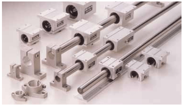
“Bearings housed in carriages and tables can ride on round shafts or square profile rails. Here’s a look at the advantages of each when an application demands guided linear motion.”
Engineers faced with a linear-motion application often turn to pre-engineered linear bearings and guides. But linear guides come in two basic shapes – round and square – and designers often struggle with which type to use. Square or profile rails once cost significantly more than round because the former need extensive grinding that is inherent to the design. But recent manufacturing advances and economies of scale let square rails now compete with round in a broad range of applications.

The criteria for choosing one over the other are no different than choosing any other machine component: define system objectives, then consider factors such as load capacity, stiffness, accuracy, smoothness, size, and overall costs. The best place to start is to look at the fundamental qualities of each type of guide.
Fundamental attributes.
Square or profile rails are flat on the top and bottom, while the sides have a concave shape with ball-conforming races where bearings roll. They typically target applications such as machine tools that require high load capacity, stiffness, and accuracy.
A profile rail’s performance comes from its inherent shape and through precise grinding of the rail ball tracks. The race on which the balls ride in the rail and carriage is only slightly larger in radius than the balls themselves. This geometry cradles the balls as they flatten slightly under load, which expands the contact area between them and the race and results in high load capacity. Substituting cylindrical rollers for ball bearings can roughly double load capacity in the same sized package.
Square rails can be preloaded from 3 to 13% of rated dynamic load. Heavy preloads apply an initial deflection to the bearings and cut deflection under load. This gives stiffness on the order of 1 to 4 μm/kN at 13% preload, for example. As a result, profile-rail bearings are roughly a factor of five stiffer under load than a round-rail assembly with its convex ball and shaft surfaces.
A key advantage of square rails is high positioning accuracy, especially useful in milling and grinding machine tools. They hold from 0.0002 to 0.001 in. over a length of 10 ft, with typical 3 to 10-μm/m parallelism between the bearing guide and rail. They also maintain this precision under moment loads; a single carriage and rail is often better suited for this than around rail.
With load capacity, stiffness, and accuracy all favoring profile rail, some engineers may look no further. However round-rail designs, with a ball-bushing bearing riding on a precision shaft, can offer several advantages over profile rails. For example, round rails are generally less expensive than square rails and are more forgiving of misalignment and poor parallelism.
Round-rail bearings also tend to operate more smoothly than profile rail. The point contact of convex surfaces between balls and rail on round types minimize scuffing. Ball bushings typically run with a slight clearance or a light preload about 1 to 2% of rated dynamic load, which also promotes smooth operation.
By comparison, profile-rail bearings with their high conformity and preloads may exhibit “notchiness” in operation. In most cases, that’s not a problem. Also, the simple seals on round bushings tend to add less drag than the wiper on profile rails. Profile-rail wipers must conform to the ball tracks for a good seal, which increases drag compared to round linear bearings.
Another advantage of round-rail bearings is the ability to run smoothly when mounted to less-than-perfect surfaces, often defined as a flatness error greater than 150 μm/m. Square-rail designs are especially sensitive to flatness errors that can cause binding and high drag that can cut life in half. Surfaces must be carefully prepared or the parts shimmed and adjusted during installation, adding to costs. In contrast, round rails can mount to welded tubular frames or directly to factory floors. Because a ball bushing is free to rotate about a round shaft, when used in pairs, one rail can sit at a slightly different elevation than the other and allow more variation in rail height than square-rail systems.
Round rails can hold a travel straightness of 0.01-in. for 10 ft. To attain this accuracy, they need to mount only at the ends, although many are supported at several points or along their full length. Round linear guides are capable of spanning gaps of 12 to 24 shaft diameters, making them useful in applications such as gantry systems and pick-andplace modules in factory automation equipment. The axis of motion is established entirely by fixing the two ends of the shaft; it doesn’t matter what the surface of the machine is like between these two points or whether there is one at all. Precision of the device depends only on the accuracy of the end-support mounting. Generally, round-rail installation is relatively easy and inexpensive.
By comparison, square profile rail are not designed to span gaps or be end supported. They are stiffer and more rigid, but need straight, continuous support with tight requirements for flatness and parallelism.
A critical parameter for profile guides is running parallelism, which is in the several-micrometer range. Unless followed closely, the bearings bind or wear prematurely. To prevent such problems, installation guides painstakingly cover mounting-surface preparation, mounting tolerances, and rail parallelism. Installation data also encompasses rail vertical offset, vertical and lateral carriage offset, mounting hole tolerances, bolt torque, and butt joints.
However, a single profile rail can support moments in all directions, eliminating the problem of aligning two rails on divergent surfaces. Applications with a wide (about 300-mm) footprint may not work with a single guide because off-center loads can induce significant moments on the rail. Before specifying a profile rail, be sure to check its moment rating and stiffness under expected moment loads.
Design considerations
Common linear-guide design parameters include load capacity, accuracy, rigidity, smoothness of travel, speed, and acceleration. They also include size, environment, and installation requirements, as well as product and installation costs. Many applications have one or two parameters that narrow the range of options for the optimal linear guide.
Try to select the type of rail before starting the machine layout. Mounting fixtures are radically different between round and square rails, and the area in which to work varies as does the load rating for the physical size. If it doesn’t work out later, changing from one brand of square rail to another, for example, is easier than changing from a square to round rail.
Square rails have higher load-life capacity, defined as the amount of load the unit handles traveling a specified distance. Under ideal conditions wear is minimal because the rail doesn’t slide but has rolling contact. When properly specified, square-rail life primarily depends on the environment and adequate lubrication.
But square rails come with some critical application and environmental deratings, typically found in manufacturers’ handbooks or design guides. These account for factors such as off-center loads, orientation, cycle times, operating environment, and type of lubrication.
Unfortunately, designers don’t consider derating factors frequently enough in the beginning design stages for either round or square rails. For example, a standard duty-cycle rating could be 4 million in. of travel. Yet after considering actual operating conditions, guidelines might recommend that a rail system not be used beyond 25 to 50% of the rated capacity.
Most major bearing manufacturers offer Web-based engineering tools and catalogs for linear roller and ball guides that contain sizing, application, and installation information. For example, NB Corporation of America (www. nbcorporation.com) offers a slide guide travel-life calculation program and guidelines on selecting linear guides. It also contains sections on allowable loads, life, rigidity and preload, operating environment, frictional resistance and required thrust, lubrication, temperature considerations, RoHS compliance, and handling precautions.
Each linear roller or ball-bearing guide has unique specifications for velocity, acceleration, tolerances, preload, and temperature range. These tools help determine static and dynamic load and moment capacities. Catalogs and Web sites also include graphs and equations for determining bearing travel life from the dynamic load rating and user-specified operating parameters.
Application considerations
Many applications can use either round or square rails, but not always. For example, mounting a square rail to a sheet-metal base may not work because the structure is not rigid enough. Likewise, round rails may not be the right choice when applications require high accuracy.
Sometimes mounting space is limited. Profile-rail bearings tend to be more compact than round ball-bushing bearings of the same load rating. But when a compact package is the driving design factor, dual-shaft linear guides are a common choice. These guides have a carriage that rides on a pair of parallel round rails, producing controlled motion from one simple unit. To maximize space savings, many dual-shaft guides can accommodate a drive such as a ball screw between the rails. The units are preassembled and ready to bolt to the mounting surface without requiring adjustments for parallelism, as with a pair of single-rail guides. That said, dual-shaft linear guides are not always a wise choice. When guiding large overhung loads, for example, it may be advisable to use two single-rail guides spaced apart.
Design flexibility is often an important consideration as well. For example, linear-guide components may need to be modified to suit a particular operation. It is generally easier to modify a round-rail system than a square one. Round shafting can be end supported and used as a structural member in a larger assembly. And round shafts can accept diameters, flats, and drilled holes both on center and radially. Ball bushings can be fit to a bore integrated directly in an adjacent component or installed in pillow blocks, which can simplify mounting and modifications.
Profile-rail linear guides offer higher rigidity than roundrail guides. But because of their rigidity, they must mount to dimensionally accurate surfaces to operate properly. Applications that require high-precision guides often have accurately machined surfaces for mounting profiled rails. However, if surfaces require a grinding operation before mounting the guides, installation expenses will increase.
And sometimes rigidity is a liability. Most non-machinetool applications instead require compliance. Compliant linear guides are not as sensitive to imperfections on mounting surfaces and are easier and less expensive to install than profile-rail guides. Packaging applications are an example of where compliant linear guides are preferred. In packaging equipment, the driving design factors include smooth travel, low installation cost, and low overall cost. Profile-rail linear guides are often wrong for these applications. Round rails with inherent compliance can be a better, more economical option
Deciding between rigidity and compliance, however, isn’t the only choice. One example is semiconductor manufacturing, where smooth operation is paramount. This application requires a linear guide that carries a low load with extremely smooth travel. While many semiconductor manufacturers use a profile-rail guide, a small round-rail guide may be better.
Durability is another important linear guide quality. Linear guides on machines are often difficult to access, and shutting down a production line due to bearing failure on a linear guide can pose a tremendous expense. For this reason, a robust design that accounts for real-life conditions and includes a healthy safety factor are a priority
One innovation to promote long-life operation is selflubricating linear guides. Many plants have extensive lubrication systems permanently connected to linear guides, or guides with grease fittings for intermittent lubrication. Self-lubricating guides reduce system cost by eliminating the need for such lubrication systems.
When choosing linear guides, however, a common mistake is using the same type in a machine with several different linear-motion requirements. Medical imagers, for example, have a scanning bed which slides into a “tunnel” that holds detector heads. When the bed stops, detector heads slide into place around the patient. Each sliding motion works independently of the other and has different requirements. The scanning bed only requires coarse adjustments, while the heads demand high precision. Here, the best choice is using high-precision guides for the detector heads and less-expensive, more-compliant linear guides for the bed.
Design errors also crop up when choosing a system to carry heavy loads. Because two parallel single-rail guides spread apart is the proper approach to carry large loads, many engineers assume it’s acceptable to use more than two rails to carry even heavier loads. One reason they’re tempted to do this is to avoid the cost of a larger rail. While increasing rail size may be more expensive, using three or more rails and carriages produces a statically indeterminate system and can lead to rough operation. Unless installation is perfect, rails and carriages will inadvertently be slightly out of line. The expense of installing such a system accurately enough to produce smooth motion will likely exceed the cost of using a larger rail.


